
Aug 31, 2026Technical Articles
Slag‑Inclusion (Sand‑Ingress) Defects in Lost‑Foam Casting
Slag‑inclusion & sand‑ingress defects in lost‑foam casting: root causes and countermeasures for coating, flask filling, pouring temperature, vacuum, gating system and molten metal purification.
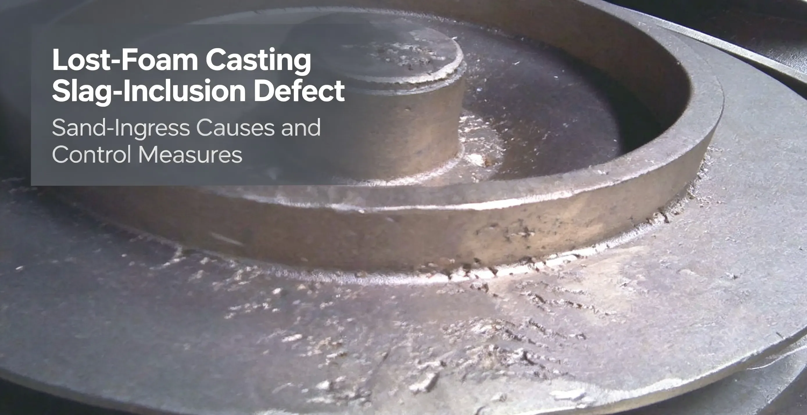
Lost‑foam casting is regarded as an eco‑friendly intensive casting process. Nevertheless, it has inherent process limitations such as foam‑pattern deformation and thermal decomposition of foamed plastic. Slag‑inclusion, also known as sand‑ingress, is a common and hard‑to‑eliminate defect, especially for flat‑shaped and disk‑shaped castings.
Defect features
Slag‑inclusions form when dry sand grains, coating fragments and foam‑pyrolysis residues are carried into castings by molten iron during pouring. After machining, white or grey‑black speckles appear on casting surfaces. White spots are mostly silica‑sand particles, while grey‑black ones originate from slag, coating debris and decomposed foam residues.
Quick pre‑inspection before shake‑out: Crack‑type burn‑on around sprue connections indicates high risk of sand‑ingress. White speckles on fractured sprue bars confirm the defect, which may cause part rejection and delay order delivery.
Root causes
- Primary causes: Cracking and spalling of coatings on foam patterns and gating‑system joints; poor sealing of the down‑sprue, allowing sand and coating fragments to be trapped in molten metal.
- Secondary factors: Improper pouring head height, pouring temperature, vacuum level, unsuitable sand grain size, and careless handling/flask‑filling operations that damage protective coatings.
Slag‑inclusion is a systematic process problem. Sand can ingress from every section of the gating system from sprue cup to casting body, so isolated single‑step adjustments cannot solve the issue completely.
Seven practical countermeasures
- Coating management: Coatings must deliver both sufficient room‑temperature strength and high‑temperature hot strength. They shall resist cracking during drying, transportation and long‑time molten‑metal erosion. Gating‑system coatings should have higher refractoriness than those for casting bodies. Ensure uniform coating thickness.
- Flask filling & vibration compaction: Avoid coating cracks or peeling at joints between down‑sprue, runner and ingate. Strengthen critical joints with thicker coating, bracing ribs or reinforcing sleeves. Support patterns steadily on bottom sand. Apply sand gently with flexible hoses first, and increase vibration amplitude only after patterns are fully buried. Do not twist gating parts during compaction. Remove loose sand from the sprue cup and seal the down‑sprue tightly before pouring.
- Pouring head, temperature & time control: Keep low pouring height and bring the ladle nozzle close to the sprue cup. Recommended temperatures: ‑ Grey iron: tapping ~1480 ℃, pouring 1380‑1420 ℃ ‑ Ductile iron: tapping ≥1500 ℃, pouring 1420‑1450 ℃ ‑ Steel castings: pouring 1480‑1560 ℃
For castings requiring 300‑500 kg molten iron, keep pouring time within 10‑20 seconds.
4.Vacuum setting: Vacuum compacts loose sand and accelerates gas discharge, but excessive vacuum draws sand and impurities through tiny coating gaps. For iron castings, maintain vacuum degree at 0.025‑0.04 MPa.
5.Gating & riser design: Adopt slag‑retaining and slag‑skimming structures in gating systems. Fit slag‑collecting risers at hot‑spots or casting ends to trap residues inside risers.
6.Molding‑sand selection: Over‑coarse grains aggravate burn‑on and slag‑inclusion; over‑fine grains reduce permeability. Traditionally, 30/50 mesh washed silica sand is widely used for iron‑based lost‑foam castings.
7.Molten‑metal purification: Implement purification throughout melting, superheating and pouring. Apply filtration technology to reduce slag entrainment from the molten‑metal source.
Additional note
Lost‑foam casting achieves good performance mainly for wear‑resistant parts, pipe fittings and box‑type castings with little or no machining. For heavily‑machined high‑quality castings, slag‑inclusion remains a key challenge. Comprehensive full‑process control is required to lower reject rates, since this defect can hardly be eliminated 100 %.
Sintered Ceramic Foundry Sand Tips for Lost‑Foam Process
Sintered ceramic foundry sand is a viable alternative filling sand for lost‑foam casting. Coarse grades such as 10/20 mesh and 20/30 mesh are commonly selected. Compared with conventional silica sand, it features high refractoriness, low thermal expansion, spherical grain shape, low breakage rate and excellent reclamation performance. Less fine powder is generated after repeated cycles, which helps mitigate inclusion‑related risks. It works well for heavy‑duty and wear‑resistant lost‑foam castings.
To know more about sintered ceramic foundry sand applied in lost‑foam, 3D‑printed sand mold, cold‑box and other foundry technologies, please visit our Sintered Ceramic Foundry Sand product page. Visit Sintered Ceramic Foundry Sand Product Page