
Aug 27, 2026Technical Articles
How to Mitigate Slag‑Inclusion Defects in Lost‑Foam Casting
Practical solutions for slag‑inclusion & sand‑ingress defects in lost‑foam casting. Guidance on coating, flask operation, pouring parameters, vacuum setting and molding sand selection.
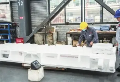
How to Mitigate Slag‑Inclusion Defects in Lost‑Foam Casting
Lost‑foam casting (EPC) is recognized as a green intensive casting technology. It delivers high dimensional accuracy and flexible production, widely used for wear‑resistant castings, pipe fittings and box‑type components. Nevertheless, influenced by pattern gasification, coating performance and on‑site operations, slag‑inclusion (sand‑ingress) remains a troublesome recurring defect. For castings requiring extensive machining, slag inclusions often lead to scrap parts and delay order delivery.
1. Manifestation of Slag‑Inclusion Defects
Slag inclusions are formed when loose sand grains, coating fragments and thermal‑decomposition residues are carried into castings by molten metal during pouring. After machining, white or grey‑black speckles appear on surfaces. White spots mostly come from silica sand particles, while grey‑black spots originate from coating debris and pyrolysis residues of foam patterns.
Defect risks can be evaluated before shake‑out. If crack‑type metal penetration occurs around the sprue cup, down‑sprue, runner and ingate connections, slag‑ingress is highly probable. Broken sprue bars showing white speckles on fracture surfaces confirm sand ingress. Flat and disk‑shaped castings are particularly vulnerable. Slag inclusions can hardly be eliminated completely, and require systematic process control to keep reject rates within acceptable limits.
2. Root Causes of Slag‑Ingress
Sand and slag inclusions stem from multiple positions throughout the gating system. Primary causes are cracking and spalling of coatings on foam patterns and joint positions, as well as poor sealing of the down‑sprue.
Other contributing factors include pouring head height, pouring temperature, vacuum level, sand grain size, pattern handling and flask filling operations. Coating damage induced by improper parameters will greatly raise slag‑inclusion risk. It should be treated as a systematic challenge rather than a single‑step problem.
3. Practical Solutions for Slag‑Inclusion Reduction
3.1 Optimize Coating Performance and Coating Application
Coating acts as the first barrier against sand ingress. Qualified coatings improve surface finish, facilitate shake‑out, resist metal penetration and discharge gas generated from foam decomposition.
For slag‑inclusion control, coatings must possess sufficient room‑temperature strength and high‑temperature hot strength. The coating layer should resist cracking and peeling during drying & handling, and remain intact under long‑time erosion of hot molten metal. Higher‑refractory coating is recommended for gating system sections. Ensure uniform coating thickness and avoid partial thin‑coating or missing coating.
3.2 Standard Flask Filling and Vibration Compaction
Inspect pattern assemblies before flask filling. No coating cracks or peeling are allowed at joints between down‑sprue‑runner, runner‑ingate and ingate‑casting. Reinforce critical joints with thicker coating, reinforcing sleeves or bracing ribs to improve rigidity of gating system.
Support patterns steadily on bottom sand. Never start vibration while patterns are suspended. Avoid direct high‑velocity sand impact onto foam patterns. Apply sand via flexible hose first, then increase vibration amplitude after patterns are fully buried. Do not twist or bend gating parts during compaction, which may tear coating layers. Clean loose sand and debris inside sprue cup before pouring, and guarantee reliable sealing of down‑sprue.
3.3 Control Pouring Head, Temperature and Pouring Time
Higher pouring head brings stronger metal erosion against gating coatings and increases sand‑ingress risk. Reduce the vertical distance between ladle nozzle and sprue cup; avoid using large ladles for small castings.
Excessively high pouring temperature accelerates coating failure. Recommended temperature ranges:
- Grey iron: tapping ~1480 ℃, pouring 1380‑1420 ℃
- Ductile iron: tapping ≥1500 ℃, pouring 1420‑1450 ℃
- Steel castings: pouring 1480‑1560 ℃
For heavy castings with 300‑500 kg molten iron, pouring time should be controlled within 10‑20 seconds.
3.4 Set Proper Vacuum Level
Vacuum compacts loose sand and accelerates gas exhausting, but higher vacuum does not equal better quality. Excessive vacuum will suck loose sand and impurities into mold cavities once tiny coating gaps exist, worsening penetration defects. For iron castings in lost‑foam process, vacuum degree is suggested at 0.025‑0.04 MPa.
3.5 Apply Slag‑Retaining Structure and Riser Design
Install slag‑trapping features within gating system. Place slag‑collecting risers at hot‑spots or casting ends to gather slag and coating residues inside risers instead of casting bodies.
3.6 Molding Sand Selection
Improper grain size aggravates slag‑inclusion and metal penetration. Over‑coarse grains enlarge inter‑granular voids; over‑fine grains reduce mold permeability. Traditionally 30/50 mesh washed silica sand is widely adopted for iron lost‑foam castings.
Note: Sintered ceramic foundry sand is also compatible for lost‑foam process. It features low breakage rate and high reclamation ratio, minimizing inclusions induced by regenerated fine powder. It suits applications requiring superior casting surface quality and high sand recycling efficiency.
3.7 Molten‑Metal Purification
Carry out metal purification throughout melting, superheating and pouring stages. Adopt filtration technology to reduce slag entrainment from the source of molten metal.
4. Sintered Ceramic Sand Selection Tips for Lost‑Foam Casting
Lost‑foam process prefers coarse‑grade sand. Common grades for sintered ceramic sand are 10/20 mesh and 20/30 mesh. Compared with silica sand, sintered ceramic sand delivers higher refractoriness and lower thermal expansion. Low grain breakage produces less fine powder after repeated cycles, lowering inclusion risks. It performs excellently for heavy‑duty and wear‑resistant lost‑foam castings.
To learn more about sintered ceramic foundry sand applications for lost‑foam, 3D‑printed sand mold, cold‑box and other foundry processes, please visit our Ceramic Foundry Sand product page. Visit Ceramic Foundry Sand Product Page