
Technical Articles
Gating System for Casting: Key Operation & Design Points
Full guide to casting gating system: pouring basin, sprue, sprue well, runner & ingate. Learn molten metal flow rules to avoid casting defects.`
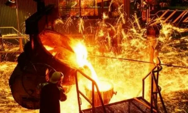
Casting pouring seems simple, yet it involves many critical details. Below is a summary of practical operation and design essentials for the casting gating system.
1. Functions of Pouring Basin
The pouring basin is a funnel-shaped external pouring gate. It can be prefabricated or formed directly inside the mold, serving as the enlarged section at the top of the sprue. Its main functions:
- Receive molten metal from the ladle to avoid splashing and overflow for easy pouring;
- Reduce direct impact of molten metal on the mold;
- Trap part of slag and impurities and prevent them from entering the sprue;
- Raise the static pressure of molten metal.
Pouring basins fall into two types: funnel type and pouring well. The funnel-shaped basin features simple structure and saves metal consumption but has poor slag trapping performance. It is commonly used together with a filter screen for better dross retention. The pouring well delivers superior slag separation. A dam at the bottom facilitates stable pouring, allowing molten metal to reach a proper flow velocity before entering the sprue. With deeper liquid level inside, it suppresses horizontal vortexes and forms vertical vortexes, which helps separate slag and bubbles.
2. Sprue: Functions & Design
The sprue guides molten metal downward from the pouring basin to the runner, ingate or directly into the mold cavity. It provides sufficient pressure so that molten metal can overcome flow resistance and fill the cavity within the required time under gravity. Common sprue shapes: tapered (wider at top, narrower at bottom), uniform cylindrical, reverse tapered (narrower at top, wider at bottom). Snake-type, sheet-type and slot sprues are also adopted for aluminum and magnesium alloy castings.
As the first channel and pressure transfer section for molten metal entering the cavity, the sprue dimension directly affects flow speed and filling time.
2.1 Structure
For die casting, the sprue normally consists of a shot sleeve and sprue bushing. Integral manufacturing is preferred. If produced separately, matched tolerance and clearance must be controlled strictly to guarantee coaxiality.
2.2 Dimension
The sprue diameter D generally matches the shot sleeve diameter and is determined by the required injection specific pressure. The sprue height H is 1/2 ~ 1/3 of diameter D. The solidified metal inside the sprue is called biscuit. For easy ejection of the biscuit from the sprue bushing, a draft angle of 1°30′ ~ 2° is machined on the inner bore within 15–25 mm near the parting line.
2.3 Flow Patterns of Molten Metal in Sand Mold Sprue
Tests show that tapered sprues (taper ratio 1/50) maintain full flow. Cylindrical sprues with constant cross-section and reverse tapered sprues operate under unfilled flow condition.
- Two flow modes in sprue: full flow and unfilled flow.
- In unfilled sprues, molten metal flows down under gravitational acceleration with a shrinking stream. The surface pressure is slightly positive, close to atmospheric pressure. The liquid stream drags surface gas downward into the rising melt inside the mold. There is no pressure difference between the stream core and mold surface gas, so gas will not be sucked into the stream; however, gas can be adsorbed and carried away by the molten metal surface.
- Sprue inlet geometry influences flow pattern. Sharp corners increase flow resistance and section contraction, easily causing unfilled flow. Sharp edges also lead to sand erosion defects in sand casting. To achieve full flow, the fillet radius at the inlet shall satisfy r ≥ d/4 (d = top diameter of sprue).
- In mass production, most gating systems are equipped with runners and ingates. Extra flow resistance from runners and ingates enables constant-section or even reverse tapered sprues to achieve full flow.
Unfilled sprues are still required in certain scenarios, for example: stepped gating systems for bottom-up sequential filling, or bottom-pour ladle application to prevent steel overflow.
Pressure measurement was carried out at upper, middle and lower positions of a constant-section sprue for gray iron sand casting (sprue height: 400 mm, diameter: 30 mm, pouring temperature: 1300 ℃). The result shows the pressure inside the sprue is slightly positive, ranging from 50 Pa to 1 kPa. Pressure near the pouring basin is higher, with a peak value up to 1.8 kPa at the initial pouring stage.
2.4 Sprue for Hot-Chamber Die Casting
The sprue of hot-chamber die casting mold is composed of the machine nozzle, sprue bushing and spreader. The extended spreader adjusts the cross-sectional area and flow direction of molten metal, and helps pull out the solidified biscuit from the fixed half mold. Recommended parameters:
- Spreader fillet radius R: 4 mm ~ 5 mm
- Sprue taper angle: 4° ~ 12°
- Spreader taper angle: 4° ~ 6°
- Annular area near spreader top: twice the ingate area
- Annular area at spreader root: 3 ~ 4 times the ingate area
- Small end diameter of sprue: approx. 1 mm larger than nozzle outlet diameter
Cooling channels are usually arranged inside the sprue bushing and spreader to match high-efficiency hot-chamber production.
2.5 Sprue Base (Sprue Well)
Molten metal hits the sprue bottom violently and generates turbulence and vortexes, which easily trigger sand wash, slag holes and oxide inclusion defects. A sprue well optimizes flow behavior:
- Buffer the impact of molten metal;
- Reduce the high-turbulence zone at the sprue-runner corner;
- Balance flow distribution to each ingate;
- Lower local resistance coefficient and pressure loss at the turning point;
- Collect gas carried by the first incoming melt and allow bubbles to escape.
The sprue well shall be properly sized and shaped with compact sand. Dry sand core or refractory brick can be placed at the bottom to resist sand erosion. Common shapes: hemispherical, truncated cone.
3. Runner
Functions of Runner
- Transfer molten metal from sprue to ingates;
- Preheat the mold with large-volume molten metal inside the runner;
- Feed shrinkage and transmit static pressure during solidification.
Runner Design Guidelines
- Cross-sectional area gradually reduces from sprue toward ingate, no abrupt change;
- Runner cross-section ≥ ingate cross-section;
- Proper thickness and length are required;
- Minimize heat loss to ensure the runner solidifies after the casting and ingate;
- Blind runners can be adopted to balance mold temperature and trap cold melt, coating residue and air.
Runner Length Calculation
Formula: L = 0.5D + (25~35) mm L = runner length (mm) D = diameter at sprue outlet (mm)
4. Ingate
A complete gating system consists of pouring basin, sprue, sprue well, runner and ingate. The ingate is the final passage for molten metal entering the mold cavity. Main functions:
- Control filling speed and flow direction;
- Adjust temperature distribution and solidification sequence of the casting;
- Provide feeding capacity. Single or multiple ingates can be designed according to casting requirements.