
Aug 25, 2026Technical Articles
3D‑Printed Sand‑Mold Casting for Narrow‑Channel Impellers (Using Sintered Ceramic Foundry Sand)
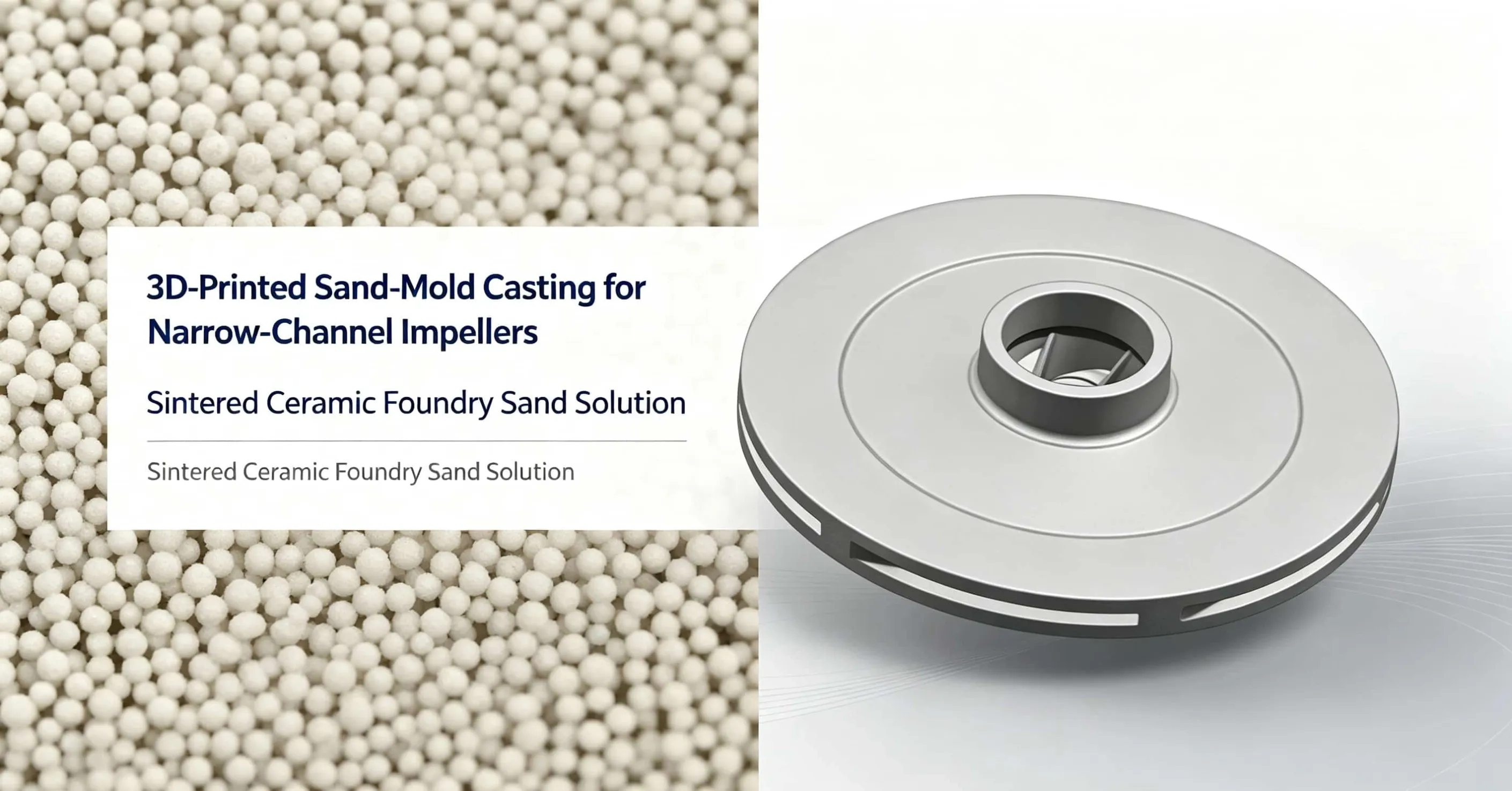
Production practice of narrow‑channel impeller castings by 3D‑printed sand‑mold technology with sintered ceramic foundry sand.
Abstract
This article presents production practice for narrow‑channel impellers manufactured by binder‑jet 3D‑printing sand‑mold casting. Sintered ceramic foundry sand replaces conventional silica sand as base material. Flow‑coating is applied for internal mold surface finishing and vertical pouring is adopted for forming. Production trials prove that castings achieve qualified surface finish and dimensional accuracy, solving typical defects of thin‑walled narrow‑flow‑path impellers.
1. Introduction
Binder‑jet 3D sand‑printing is an additive manufacturing technology based on droplet jetting. The workflow includes sand recoating, mixing base sand with curing agent, selective resin‑binder jetting and post‑print cleaning. When jetted resin contacts sand pre‑mixed with curing agent, sand grains bond and solidify into complete molds and cores.
This digital manufacturing route eliminates hard‑tooling patterns. Complex integrated sand‑cores can be directly printed, avoiding cumulative dimensional errors from manual core assembly. It improves mold precision and reduces dimensional out‑of‑tolerance risks for finished castings.
With wider adoption of 3D sand printing, foundries gain greater design freedom. The process cuts mold investment and enables fast, low‑cost production of high‑quality castings with intricate internal passages. It overcomes limitations where cores cannot be extracted from closed geometry, shortens lead‑time for new‑product iterations and enhances manufacturing flexibility for small‑batch custom parts.
2. Technical Requirements for Impeller Casting
Impeller components demand balanced hydrodynamic performance, mechanical strength and toughness with optimized geometry to deliver high efficiency, low noise and low energy loss. Manufacturing requires stable material quality, precise machining and strict process control to guarantee dimensional tolerance and surface roughness.
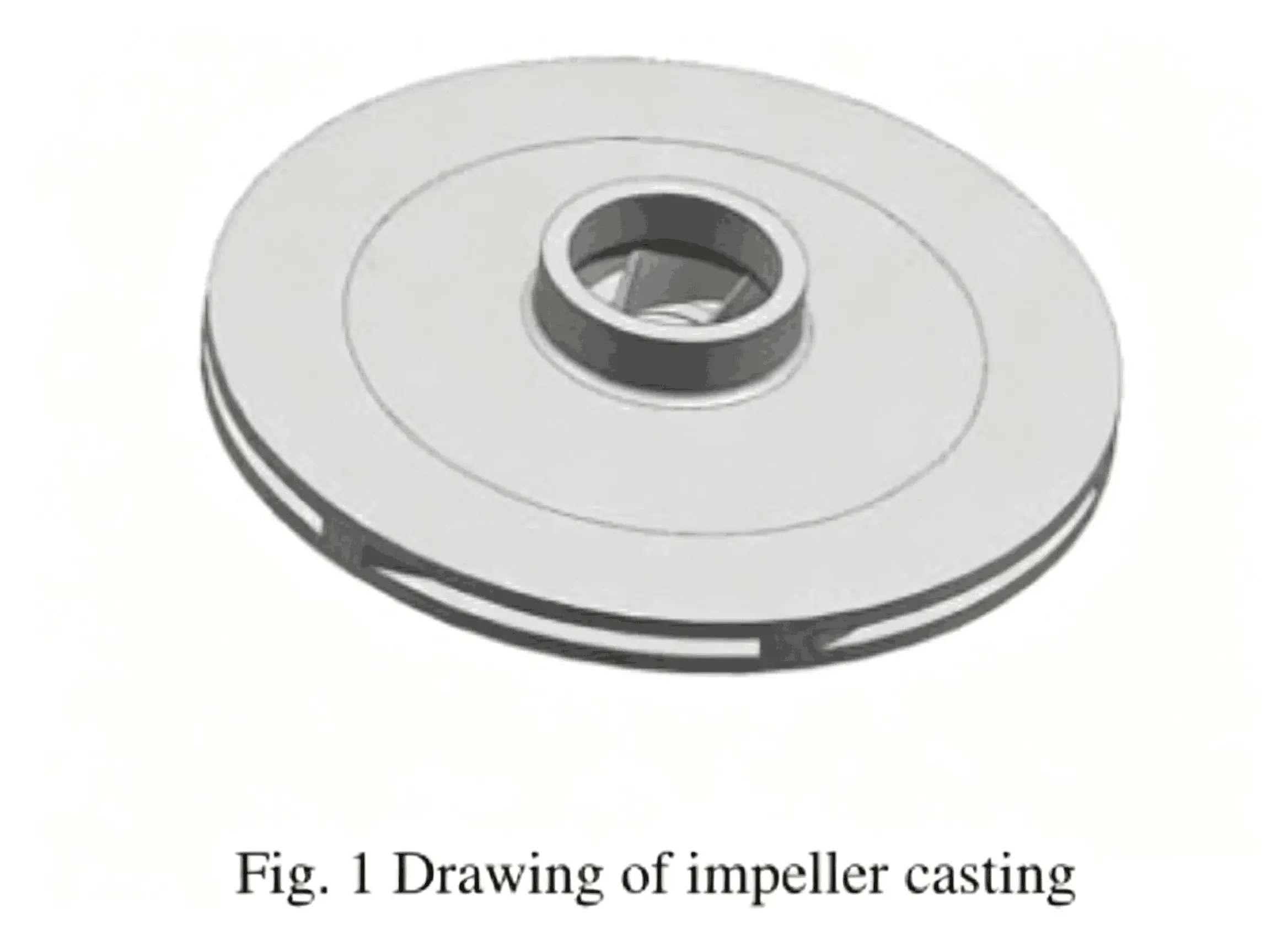
The trial‑produced impeller is made of HT250 gray cast iron, with a gross casting weight of 16 kg, maximum outer diameter 339 mm and overall height 96 mm. The minimum blade wall thickness reaches only 2 mm, cover‑plate thickness 5 mm, and water‑outlet width is controlled at (6±0.2) mm. Dimensional tolerance for flow‑passage surfaces shall reach CT9 grade. Castings must be free from cold shuts, metal penetration, cracks, porosity, slag inclusions and shrinkage cavities.
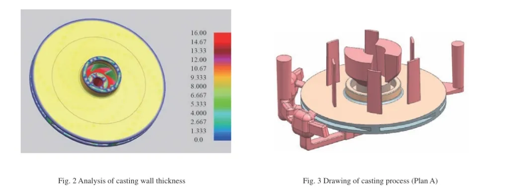
Narrow‑channel impellers typically feature outlet widths between 4‑8 mm and overall diameters above 300 mm. Large‑diameter profiles are combined with fragile thin‑section cores, which bring challenges including low core strength, poor collapsibility and difficult gas venting. Core deformation or fracture easily causes core‑shift, sand‑inclusion and porosity defects, raising overall casting difficulty. Wall‑thickness simulation analysis is essential before process development.
Two competing process schemes (Plan A and Plan B) were evaluated in trials.
- Plan A: Step‑gating bottom filling for quiet molten‑metal filling, plus top ingates for thin‑cover‑plate forming. Over‑flow and feed‑risers are designed for venting and feeding, with vent tabs fitted at blade‑to‑cover‑plate junctions. Numerical filling simulation was performed to predict air‑entrapment risk zones.
- Plan B: Vertical‑pouring layout. Impeller cover‑plates are placed vertically, with molten iron injected between two side cover‑plate cores. A closed gating system ensures fast, stable filling especially for thin blade sections. Over‑flow risers are arranged on casting tops for degassing and feeding. Filling simulation validates the fluid‑flow and pressure distribution.
3. 3D‑Printed Sand‑Mold Solution with Sintered Ceramic Sand
Molds are fabricated with sintered ceramic sand compounded with furan resin and curing agent. The printed sand‑mold obtains tensile strength of 1.4‑1.9 MPa and gas evolution below 12 mL/g.
- Plan A: Split upper‑and‑lower mold construction. Annular‑boss fire‑stop grooves serve for positioning, and core‑vent holes are arranged in central bores. High printing precision minimizes mold‑joint gaps and ensures alignment stability. Handling cutouts are integrated into each mold segment to facilitate shake‑out, coating, transportation and mold assembly.
- Plan B: Horizontal printing with vertical‑pouring configuration. Side‑wall cover‑plate cores are placed on two sides, while integral blade‑passage cores sit in the middle. Vent channels run from the central core circle through side‑wall cores and connect to top atmospheric vents.
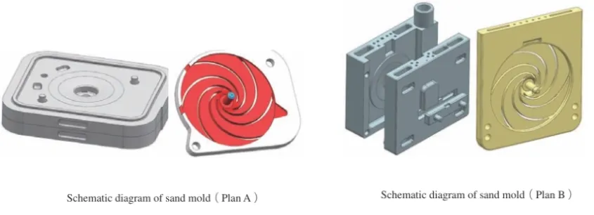
3D printing enables one‑piece fabrication of complex impeller‑passage cores. Dimensional accuracy of printed molds can be controlled within ±0.2 mm, greatly boosting casting precision. Mold joints are sealed with mould‑sealing compound after closing and locked with dedicated fixtures.
Coating process: Flow‑coating technology is adopted to achieve high‑quality inner‑surface finish for flow‑passages. Coating thickness is strictly controlled within 0.15‑0.25 mm by Baumé meter and comb‑type wet‑film thickness gauge. Water‑based composite refractory coating is used to mitigate metal penetration risk. Coated molds are dried inside kilns at 100‑130 °C for 2‑3 hours.
Benefit of sintered ceramic sand for this application: Compared with silica sand, sintered ceramic sand features low thermal expansion, high refractoriness and good collapsibility for narrow intricate passages. It helps suppress veining, reduces metal‑penetration tendency inside thin flow‑channels and improves shake‑out performance for fragile fine‑feature cores.
4. Production Validation & Process Comparison
For pouring parameters: tapping temperature of molten iron ≥1500 °C, pouring temperature set at 1430 °C ±10 °C, pouring time approx. 8 seconds. Weights are applied for Plan A molds; dedicated clamps secure Plan B assemblies.
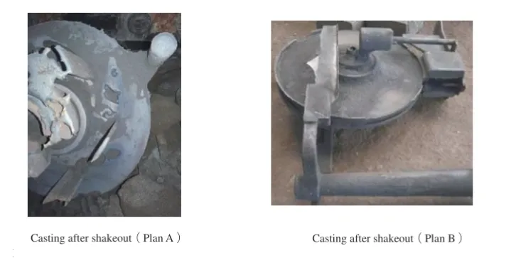
- Plan A: Final castings suffered unacceptable porosity, core‑shift and sand‑inclusion defects and were rejected. Conventional horizontal pouring cannot resolve inherent problems of thin blade cores: low strength and poor venting lead to core swelling or fracture, triggering core‑shift, sand‑inclusion or mis‑run defects.
- Plan B (vertical pouring): Completed castings show no obvious penetration, porosity or mis‑run defects. After riser cutting, grinding and shot‑blasting, dimensional inspection confirms CT9 tolerance grade. Internal flow‑passage surface roughness Ra reaches 18‑22 μm, fully satisfying acceptance criteria.
Following successful trials on the prototype impeller, the vertical‑pouring + 3D‑printing workflow was generalized to other narrow‑channel impeller variants. An improved layout with two‑cavity‑per‑mold further raises production efficiency.
Cost & lead‑time comparison (small‑batch trial for two castings)
- Conventional sand casting: Mold cost ~20 000, mold lead‑time 22 days; moulding, coring & core assembly take additional 3‑5 days.
- 3D‑printed sand mold with sintered ceramic sand: Total cost around 3 000; total turnaround from CAD model to finished casting is only 7 days.
5. Conclusions
- 3D‑printed integral sand‑cores made with sintered ceramic sand deliver superior casting quality. Impeller dimensional accuracy is greatly improved, flow‑passage surface roughness is reduced and internal‑channel geometry is better preserved. Dimensional tolerance of narrow passages can be held within ±0.2 mm.
- Vertical‑pouring process enables successful casting of narrow‑channel impellers with outlet widths of 4‑8 mm. This layout solves venting difficulties for ultra‑thin blade cores and mitigates failures caused by low core strength. Complete filling of 2 mm thin‑wall blades can be reliably achieved to meet high‑performance impeller requirements.
- 3D‑printing with sintered ceramic sand lowers moulding and coring complexity for narrow‑channel impellers. It supports agile manufacturing for intricate geometries with minimal waste material. Obvious advantages in cost and delivery speed are realized for single‑piece and small‑batch production.
To learn more about the application of sintered ceramic foundry sand in 3D printed molds, cold‑box, resin‑coated sand and other foundry processes, please visit our Sintered Ceramic Sand product page. Visit Sintered Ceramic Sand Product Page